DISCLAIMER: Please be sure you understand how to safely do wiring with line voltage or hire a professional who does.
Be sure to read the intro post first.
Wiring Diagram
Now that we have a grasp of how in-floor heating sensors work and the device we will use to turn the floor heat ON
and OFF we can start wiring up our IOT device. The diagram below should provide the high level overview of how we
wire electricity from the circuit breaker panel (LINE) to the resistive floor heating circuit (LOAD ). The Shelly
Add-On is then wired to the NTC sensor via the ground (GND) and the voltage reading circuit.
 +----------------+
 |      LINE      |
 |  Hot   Neutral |   +-------------+-------------+
 +---+-------+----+   |    Shelly   |   Shelly    |   +------------+
     |       |        |   Plus 1PM  |   Add-On    |   |   Sensor   |
     |       |        +-------------+-------------+   +----+--+----+
     |       +--------+ N           |             |        |  |
     |                |             |         GND +--------+  |
     |   +------------+ N           |             |           |
     |   |            |             |   Analog IN +-----------+
     +---|------------+ L           |             |           |
         |            |             | VREF+R1 OUT +-----------+
         |        +---+ O           |             |
         |        |   +-------------+-------------+
    +----+--------+--+
    | Neutral    Hot |
    |      LOAD      |
    +----------------+
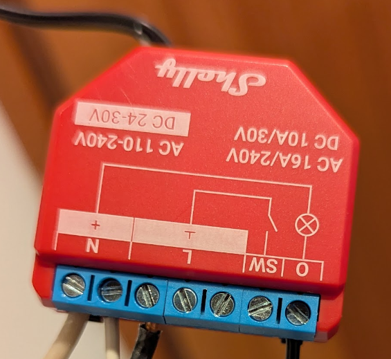
Here is a picture of the LINE and LOAD wiring.
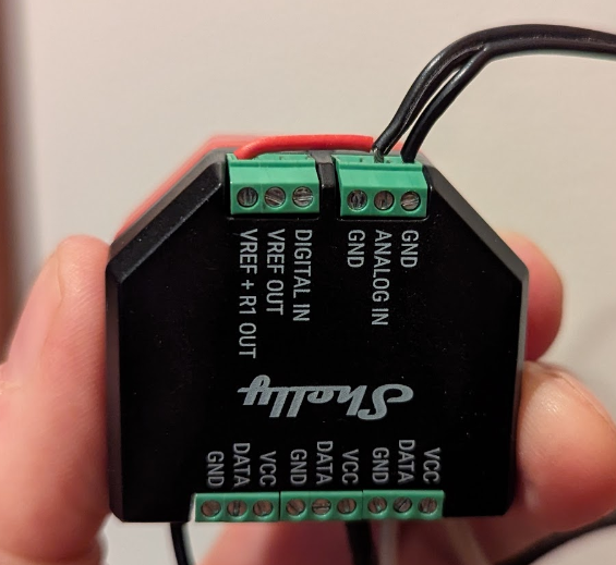
And a picture of the add-on wiring. The black wires come from the sensor, and the red wire connects the VREF-R1 OUT
with the ANALOG IN.
Next
Next read about how to run code on the Shelly 1PM.